Profinet Gateway with HMS AB6675-C

https://drive.google.com/drive/folders/1LepeQXR4SIxZWcZ_F_MjXX9yPu24hadA?usp=sharing Dear HMS Technical Support,
I am designing a universal PROFINET gateway carrier PCB based on the Anybus CompactCom B40 AB6675-C brick. The gateway is intended to bridge field-side industrial protocols — primarily Modbus RTU over RS-485, SSI and ABZ encoder interfaces, and analog process signals — to PROFINET IRT via the AB6675-C. The host MCU is an STM32H743IIT6 communicating with the module over SPI (OM0=HIGH, OM1=LOW, OM2=LOW, OM3=pull-down).
I would appreciate a review of the schematic before proceeding to PCB layout, and have the following specific questions:
1. MD0 module-presence detection
I have routed host pin H30 (MD0) to an external MCU GPIO via J2 pin 11, with a 10kΩ pull-up to +3.3V. The intended behavior is that MD0 reads LOW when the module is installed (module pulls the line down) and HIGH when the module is absent (pull-up takes the line high).
However, during the design review process, there was some confusion about the expected behavior of MD0. The Anybus CompactCom B40 Hardware Design Guide description of this pin was found ambiguous — specifically regarding whether the module actively pulls MD0 LOW when installed, or whether the line state depends on some other condition. Could you confirm the exact electrical behavior of MD0 when the module is installed and when it is removed, and confirm that a 10kΩ pull-up to +3.3V is the correct arrangement for presence detection?
2. ASI interface pins (H19/H20)
In the current design, host pin H19 (A12/ASI_RX) is tied to +3.3V and host pin H20 (A13/ASI_TX) is left unconnected, as the ASI interface is not being used. Is this the correct treatment for unused ASI pins, or should they be handled differently?
3. MI0/SYNC (H54)
Host pin H54 (MI0/SYNC) is routed to J2 pin 12 for optional synchronization input to the MCU. Is there anything specific required on this line when synchronization is not being used — pull-up, pull-down, or leave floating?
4. IRQ pull-up value
A single 10kΩ pull-up resistor (R_IRQ1) is placed on the IRQ line (host pin H38) to +3.3V. Is 10kΩ appropriate for this signal, or does HMS recommend a different value for reliable operation at SPI speeds up to 50MHz?
5. General schematic review
I would be grateful if you could review the attached schematic for any design errors or deviations from the recommended application circuit in HMSI-27-230 Design Guide v3.14.
Thank you for your time. I am happy to provide the full KiCad project files if that would be helpful.
Best regards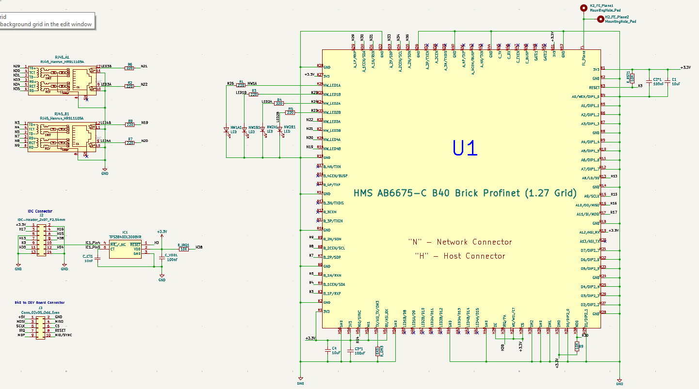
-
正式なコメント

Hi Igor
This post is regarding a design with our CompactCom embedded networking solution so you are addressing the wrong audience in this Anybus Gateways section of the forum.
My suggestion is that you visit the Developers' Portal on the HMS Networks website and there you can directly request a hardware review from the team.
https://www.hms-networks.com/embedded-network-interfaces/developer-portal/hardware-design
If you are developing with the CompactCom then we at HMS are here to help and support you. Alternatively, please make direct contact via the sales channel where you purchased the CompactCom and they can put you in touch with one of our Applications Engineering team who can guide and answer questions for you.Thank you
Siobhan
サインインしてコメントを残してください。
コメント
1件のコメント