APPLICABLE PRODUCTS
Anybus Defender Series 4000 and up
VERSIONS USED IN THIS ARTICLE
- Anybus Defender 2.5.2-2025111723
Anybus Defender – Configure the Defender as an NTP Server
Introduction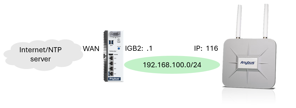
The Anybus Defender can be used as a local NTP server so that devices on an industrial network can obtain their time from the Defender instead of communicating directly with an external NTP server.
In this example:
| Device / Interface | IP Address |
|---|---|
| Anybus Defender LAN2 | 192.168.100.1/24 |
| Client Device | 192.168.100.116/24 |
| NTP Server used by device | 192.168.100.1 |
| NTP Protocol | UDP |
| NTP Port | 123 |
1. Configure LAN2
On the Anybus Defender go to Interfaces -> Assignments, configure LAN2/igb2 with:
IP Address: 192.168.100.1
Subnet:     /24
The client device must be connected to the LAN2 network.
In this example:
Device IP: 192.168.100.116
Both devices are therefore in:
192.168.100.0/24
2. Configure the Defender NTP Service
The Defender must first have its own valid time source before it can provide time to devices on LAN2.
2.1 Configure the Defender Time Settings
Go to:
System → General Setup
Locate the time settings.
Configure the correct Time Zone for the Defender.
Under Time Servers, enter the NTP server or servers that the Defender should use to synchronize its own clock.
This can be:
- An internal company NTP server
- A local NTP server on another network
- An external NTP server if Internet access is available
The Defender will use these servers to maintain its own system time.
Save the configuration.
2.2 Open the NTP Server Configuration
Go to:
Services → NTP
This page controls the NTP service running on the Defender.
The NTP service can perform two functions:
- Synchronize the Defender's clock with upstream NTP servers.
- Respond to NTP requests from devices using the Defender as their NTP server.
2.3 Select the NTP Interface
Under Interface, select the interface on which the Defender should provide NTP service.
For this example, select:
LAN2LAN2 has the address:
192.168.100.1This allows devices connected to LAN2 to use 192.168.100.1 as their NTP server.
If the Defender also needs to reach its upstream NTP server through another interface, such as WAN, that interface may also need to be selected depending on the network configuration.
Do not expose the NTP service on interfaces where it is not required.
2.4 Configure the Upstream Time Servers
Under Time Servers, verify that the upstream NTP servers are listed.
These are the servers that the Defender itself will use as its time source.
If the servers configured under System → General Setup are already shown here, they can normally be left unchanged.
Additional NTP servers can be added if required.
For example:
Company NTP Server
        or
External NTP Server
The Defender synchronizes against these servers and then provides its synchronized time to the devices on LAN2.
2.5 Save the NTP Configuration
Click:
Save
and apply the configuration if prompted.
The Defender is now configured to:
- Maintain its own system time using an upstream NTP source.
- Listen for NTP requests on LAN2.
- Provide time to devices using
192.168.100.1as their NTP server.
3. Create the LAN2 Firewall Rule
Go to:
Firewall → Rules → LAN2
Create a new rule.
Configure:
| Setting | Value |
|---|---|
| Action | Pass |
| Interface | LAN2 |
| Address Family | IPv4 |
| Protocol | UDP |
| Source | LAN2 net |
| Source Port | Any / * |
| Destination | LAN2 address |
| Destination Port | 123 (NTP) |
| Description | Allow LAN2 devices to Defender NTP |
Save and apply the configuration.
The finished rule should effectively be:
IPv4 UDP

Source:
LAN2 net
Source Port: Any

Destination:
LAN2 address
Destination Port: 123 (NTP)
Why LAN2 address is used
LAN2 adress represents the Defender's own IP address on that interface.
In this configuration:
LAN2 address = 192.168.100.1
The rule does not allow LAN2 devices to access arbitrary external NTP servers.
4. Configure the Client Device
On the device at 192.168.100.116, configure its NTP server as:
NTP Server: 192.168.100.1
The device will then request its time from the Anybus Defender instead of directly contacting an external NTP server.
Final Configuration
Anybus Defender LAN2
IP Address: 192.168.100.1/24
Client Device
IP Address: 192.168.100.116/24
NTP Server: 192.168.100.1
LAN2 Firewall Rule
Action:           Pass
Protocol:         IPv4 UDP
Source:           LAN2 net
Source Port:      Any
Destination:      LAN2 address
Destination Port: 123 (NTP)
This allows devices on LAN2 to use the Anybus Defender as their local NTP server while limiting the firewall rule specifically to NTP traffic directed at the Defender itself.
© HMS Networks AB 2026