APPLICABLE PRODUCTS
Anybus Defender Series 4000 and up
VERSIONS USED IN THIS ARTICLE
- Anybus Defender 2.5.2-2025111723
Anybus Defender – Configure Outbound NAT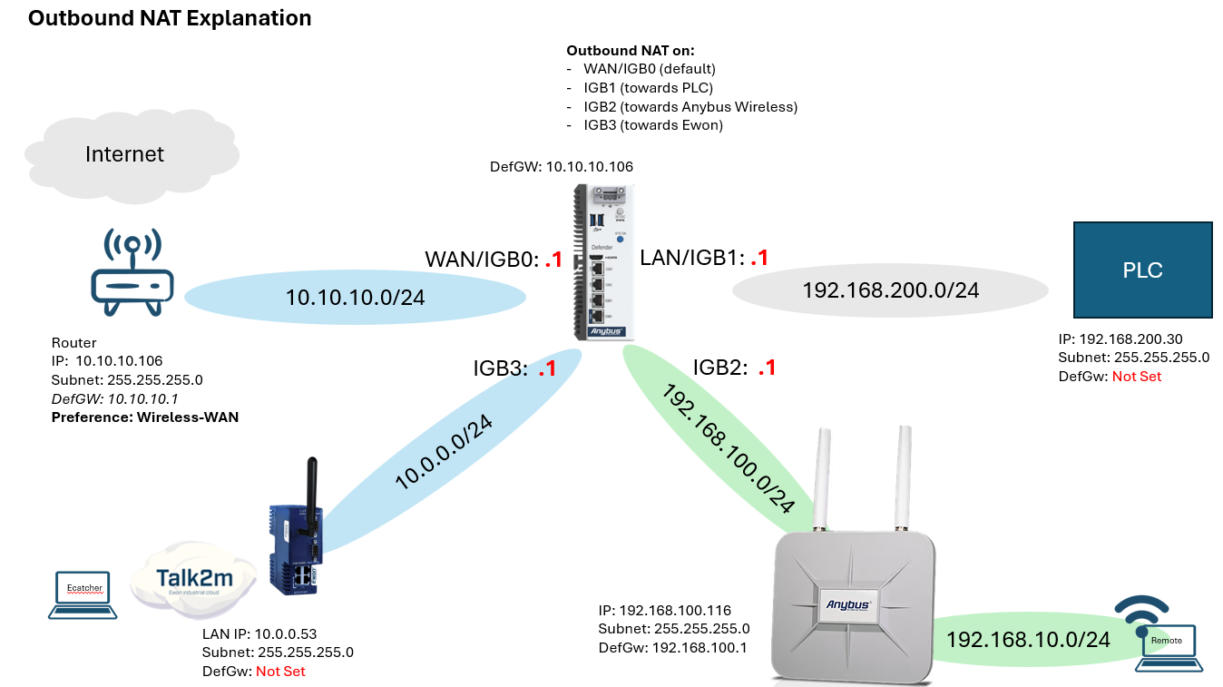
This guide explains how to configure Outbound NAT on the Anybus Defender when a device on the WAN network needs to communicate with device on the LAN networks, while the WAN device does not route towards the Defender interface.
The Defender will change the source IP address of each IP packet to its own and keep a mapping table to where traffic must be routed.
WAN interface sets Outbound NAT by default, when a default GW is configured on the Defender.
For LAN and Other interfaces Outbound NAT must be configured manually when required.
Outbound NAT is required when:
- The device does not have the default Gateway pointed towards the Defender's interface
- Another interface has preference and no static routes are present on the device, pointing the networks behind the Defender to the Defender interface
- Device lacks capability to have Default Gateway configured
Instructions
1. Example Network
| Interface | Physical Port | Defender IP | Network | Connected Device |
| WAN | IGB0 | 10.10.10.1/24 | 10.10.10.0/24 | Upstream Router |
| LAN | IGB1 | 192.168.200.1/24 | 192.168.200.0/24 | PLC |
| LAN2 | IGB2 | 192.168.100.1/24 | 192.168.100.0/24 | Anybus Wireless |
| LAN3 | IGB3 | 10.0.0.1/24 | 10.0.0.0/24 | Ewon |
Example devices:
| Device | IP Address | Default Gateway |
| PLC | 192.168.200.30/24 | Not configured |
| Anybus Wireless WAN1 | 192.168.100.116/24 | 192.168.100.1 |
| Wireless Remote Network | 192.168.10.0/24 | Provided by Anybus Wireless |
| Ewon | 10.0.0.53/24 | Not configured |
The Defender uses:
10.10.10.106
as its default gateway on WAN.
2. Communication Used in This Example
The following communication will be configured:
| Source | Destination | Purpose |
| Wireless Remote Network 192.168.10.0/24 | PLC 192.168.200.30 | Ping and Siemens S7 |
| Ewon 10.0.0.53 | PLC 192.168.200.30 | Ping and Siemens S7 |
| Ewon 10.0.0.53 | Anybus Wireless 192.168.100.116 | HTTPS |
| Wireless Remote Network 192.168.10.0/24 | Ewon 10.0.0.53 | HTTPS |
The important point when creating an Outbound NAT rule is:
The Outbound NAT interface is the interface where the traffic leaves the Defender.
3. Anybus Wireless NAPT
The Anybus Wireless provides DHCP addresses to remote wireless clients on:
192.168.10.0/24
NAPT is enabled on its WAN1 interface.
The WAN1 address toward the Defender is:
192.168.100.116
A remote wireless client with:
192.168.10.100
pinging the Defender LAN2 address:
192.168.100.1
appeared on the Defender as:
192.168.100.116 > 192.168.100.1: ICMP echo request
192.168.100.1 > 192.168.100.116: ICMP echo reply
This confirms that the Anybus Wireless performs NAPT before the traffic reaches the Defender.
So, although the actual remote client uses:
192.168.10.100
the Defender sees the source as:
192.168.100.116
The traffic path is therefore:
Remote PC
192.168.10.100
      |
      v
Anybus Wireless
NAPT on WAN1
      |
      | Source translated to
      | 192.168.100.116
      v
Defender LAN2
192.168.100.1
Because of this, Defender firewall and Outbound NAT rules for traffic originating from the remote wireless network should use:
192.168.100.116/32
as the source.
4. How Outbound NAT Works
Normally, routing does not change the source IP address.
For example, after the Anybus Wireless has performed NAPT, traffic reaching the Defender from a remote wireless client appears as:
Source: 192.168.100.116
Destination: 192.168.200.30
If the Defender routed this directly to the PLC without another NAT translation, the PLC would receive:
192.168.100.116 -> 192.168.200.30
The PLC would then need a route back to:
192.168.100.0/24
In this example, however, the PLC does not have a default gateway.
Outbound NAT on the Defender changes the source again when the packet leaves through LAN.
The PLC therefore receives:
192.168.200.1 -> 192.168.200.30
192.168.200.1 is the Defender's LAN interface address.
Because the translated source is on the same subnet as the PLC, the PLC can reply directly to the Defender.
The Defender keeps track of the NAT connection and forwards the response back toward the Anybus Wireless.
5. Selecting the Correct Outbound NAT Interface
For Outbound NAT, select the interface where the traffic exits the Defender.
For example:
Remote PC
    |
Anybus Wireless
    |
   LAN2
    |
 Defender
    |
   LAN
    |
   PLC
The traffic:
- Enters the Defender through LAN2
- Leaves the Defender through LAN
Therefore:
| Function | Interface |
| Firewall Rule | LAN2 |
| Outbound NAT Rule | LAN |
6. WAN Outbound NAT
WAN is configured with:
- WAN IP: 10.10.10.1/24
- Default Gateway: 10.10.10.106
Because WAN has the Defender's default gateway, Outbound NAT toward WAN is handled automatically.
A manually created Outbound NAT rule for WAN is therefore not required.
The following sections cover manual Outbound NAT for:
- LAN
- LAN2
- LAN3
7. Configure Outbound NAT
Go to:
Firewall → NAT → Outbound
Select Hybrid Outbound NAT mode that allows manual rules to be created while keeping automatically created rules.
8. Outbound NAT – Remote Wireless to PLC
Remote clients use:
192.168.10.0/24
but because the Anybus Wireless performs NAPT, the Defender sees their traffic as coming from:
192.168.100.116
The PLC is:
192.168.200.30
Traffic going to the PLC leaves the Defender through LAN.
Create:
| Setting | Value |
| Name / Description | Remote Wireless to PLC |
| Interface | LAN |
| Protocol | Any |
| Source | 192.168.100.116/32 |
| Destination | 192.168.200.30/32 |
| Translation / Address | Interface address |
The Defender's LAN address is:
192.168.200.1
The complete translation is therefore approximately:
Remote client:
192.168.10.100
After Anybus Wireless NAPT:
192.168.100.116 -> 192.168.200.30
After Defender Outbound NAT:
192.168.200.1 -> 192.168.200.30
The PLC can reply directly to 192.168.200.1.
9. Outbound NAT – Ewon to PLC
The Ewon is:
10.0.0.53
The PLC is:
192.168.200.30
Traffic going to the PLC leaves the Defender through LAN.
Create:
| Setting | Value |
| Name / Description | Ewon to PLC |
| Interface | LAN |
| Protocol | Any |
| Source | 10.0.0.53/32 |
| Destination | 192.168.200.30/32 |
| Translation / Address | Interface address |
The source changes from:
10.0.0.53
to:
192.168.200.1
Therefore:
Before NAT:
10.0.0.53 -> 192.168.200.30
After NAT:
192.168.200.1 -> 192.168.200.30
10. Outbound NAT – Ewon to Anybus Wireless
The Ewon needs to access the Anybus Wireless management address:
192.168.100.116
This traffic leaves the Defender through LAN2.
Create:
| Setting | Value |
| Name / Description | Ewon to Anybus Wireless |
| Interface | LAN2 |
| Protocol | Any |
| Source | 10.0.0.53/32 |
| Destination | 192.168.100.116/32 |
| Translation / Address | Interface address |
The Defender's LAN2 address is:
192.168.100.1
Therefore:
Before NAT:
10.0.0.53 -> 192.168.100.116
After NAT:
192.168.100.1 -> 192.168.100.116
11. Outbound NAT – Remote Wireless to Ewon
A remote wireless client uses an address such as:
192.168.10.100
The Anybus Wireless performs NAPT before the traffic reaches the Defender.
The Defender therefore sees:
192.168.100.116
as the source.
The Ewon is:
10.0.0.53
Traffic to the Ewon leaves through LAN3.
Create:
| Setting | Value |
| Name / Description | Remote Wireless to Ewon |
| Interface | LAN3 |
| Protocol | Any |
| Source | 192.168.100.116/32 |
| Destination | 10.0.0.53/32 |
| Translation / Address | Interface address |
The Defender's LAN3 address is:
10.0.0.1
Therefore:
Remote client:
192.168.10.25
After Anybus Wireless NAPT:
192.168.100.116 -> 10.0.0.53
After Defender Outbound NAT:
10.0.0.1 -> 10.0.0.53
The Ewon can reply directly to 10.0.0.1.
12. Final Outbound NAT Configuration
| Name / Description | Interface | Source | Destination | Translation / Address |
| Remote Wireless to PLC | LAN | 192.168.100.116/32 | 192.168.200.30/32 | Interface address |
| Ewon to PLC | LAN | 10.0.0.53/32 | 192.168.200.30/32 | Interface address |
| Ewon to Anybus Wireless | LAN2 | 10.0.0.53/32 | 192.168.100.116/32 | Interface address |
| Remote Wireless to Ewon | LAN3 | 192.168.100.116/32 | 10.0.0.53/32 | Interface address |
13. Firewall Rules
Firewall rules determine whether the Defender permits the connection.
For the examples in this guide:
- Outbound NAT is based on the outgoing interface.
- Firewall rules are placed on the incoming interface.
13.1 LAN2 Firewall Rules
Remote wireless traffic reaches the Defender through LAN2.
Because NAPT is enabled on the Anybus Wireless WAN1 interface, the Defender sees the source as:
192.168.100.116
Go to:
Firewall → Rules → LAN2
Allow Remote Wireless to Ping PLC
| Setting | Value |
| Action | Pass |
| Interface | LAN2 |
| Address Family | IPv4 |
| Protocol | ICMP |
| Source | 192.168.100.116/32 |
| Destination | 192.168.200.30/32 |
| Description | Allow Remote Wireless to ping PLC |
Allow Remote Wireless S7 Access to PLC
| Setting | Value |
| Action | Pass |
| Interface | LAN2 |
| Address Family | IPv4 |
| Protocol | TCP |
| Source | 192.168.100.116/32 |
| Source Port | Any |
| Destination | 192.168.200.30/32 |
| Destination Port | 102 |
| Description | Allow Remote Wireless S7 access to PLC |
Allow Remote Wireless HTTP Access to Ewon
| Setting | Value |
| Action | Pass |
| Interface | LAN2 |
| Address Family | IPv4 |
| Protocol | TCP |
| Source | 192.168.100.116/32 |
| Source Port | Any |
| Destination | 10.0.0.53/32 |
| Destination Port | 80 |
| Description | Allow Remote Wireless HTTP access to Ewon |
13.2 LAN3 Firewall Rules
Traffic originating from the Ewon enters the Defender through LAN3.
Go to:
Firewall → Rules → LAN3
Allow Ewon to Ping PLC
| Setting | Value |
| Action | Pass |
| Interface | LAN3 |
| Address Family | IPv4 |
| Protocol | ICMP |
| Source | 10.0.0.53/32 |
| Destination | 192.168.200.30/32 |
| Description | Allow Ewon ping to PLC |
Allow Ewon S7 Access to PLC
| Setting | Value |
| Action | Pass |
| Interface | LAN3 |
| Address Family | IPv4 |
| Protocol | TCP |
| Source | 10.0.0.53/32 |
| Source Port | Any |
| Destination | 192.168.200.30/32 |
| Destination Port | 102 |
| Description | Allow Ewon S7 access to PLC |
Allow Ewon HTTPS Access to Anybus Wireless
| Setting | Value |
| Action | Pass |
| Interface | LAN3 |
| Address Family | IPv4 |
| Protocol | TCP |
| Source | 10.0.0.53/32 |
| Source Port | Any |
| Destination | 192.168.100.116/32 |
| Destination Port | 443 |
| Description | Allow Ewon HTTPS access to Anybus Wireless |
14. Configure Routes for eCatcher Remote Access
For an eCatcher PC to access devices located behind the Anybus Defender, both the eCatcher PC and the Ewon Flexy must know where the Defender networks are located.
The communication path is:
eCatcher PC
      |
      | Talk2M VPN
      v
Ewon Flexy
10.0.0.53
      |
      | Gateway 10.0.0.1
      v
Anybus Defender LAN3
10.0.0.1
      |
      +----------------------+
      |                      |
      v                      v
LAN / PLC                LAN2 / Wireless
192.168.200.30           192.168.100.116
The eCatcher PC must first send traffic for the Defender networks into the Talk2M VPN.
The Ewon must then forward that traffic to the Defender.
14.1 Add Routes on the eCatcher PC
When connected through eCatcher, determine the Talk2M VPN IP address of the Ewon.
This is different from the Ewon LAN address 10.0.0.53.
The route on the PC must use the Ewon VPN address as the gateway.
Open Command Prompt as Administrator.
Route to the PLC Network
Run:
route -p add 192.168.200.0 mask 255.255.255.0 <EWON_VPN_IP>
For example, if the Ewon VPN address is:
10.210.179.72
use:
route -p add 192.168.200.0 mask 255.255.255.0 10.210.179.72
This tells Windows:
192.168.200.0/24
        |
        v
Talk2M / Ewon VPN
Route to the Anybus Wireless Network
Also add:
route -p add 192.168.100.0 mask 255.255.255.0 <EWON_VPN_IP>
Using the same example:
route -p add 192.168.100.0 mask 255.255.255.0 10.210.179.72
The PC now knows that both Defender networks are reached through the Ewon VPN connection.
The resulting PC routes are:
| Destination | Mask | Gateway |
| 192.168.200.0 | 255.255.255.0 | Ewon Talk2M VPN IP |
| 192.168.100.0 | 255.255.255.0 | Ewon Talk2M VPN IP |
You can verify the routes with:
route print
You should see entries for:
192.168.200.0
192.168.100.0
pointing toward the Ewon VPN IP.
14.2 Add Static Routes on the Ewon Flexy
The Ewon receives the traffic from Talk2M, but it must also know that the PLC and Anybus Wireless networks are located behind the Defender.
The Ewon LAN address is:
10.0.0.53
The Defender LAN3 address is:
10.0.0.1
Go to the Ewon routing configuration:
Setup → System → Communication → Networking → Routing → Static Routes
Add the following routes.
Route to the PLC Network
| Setting | Value |
| Destination | 192.168.200.0 |
| Mask | 255.255.255.0 |
| Gateway | 10.0.0.1 |
| Hops | 1 |
This tells the Ewon:
192.168.200.0/24
        |
        v
Defender 10.0.0.1
Route to the Anybus Wireless Network
| Setting | Value |
| Destination | 192.168.100.0 |
| Mask | 255.255.255.0 |
| Gateway | 10.0.0.1 |
| Hops | 1 |
This tells the Ewon:
192.168.100.0/24
        |
        v
Defender 10.0.0.1
The completed Ewon routing table should therefore contain:
| Destination | Mask | Gateway | Hops |
| 192.168.200.0 | 255.255.255.0 | 10.0.0.1 | 1 |
| 192.168.100.0 | 255.255.255.0 | 10.0.0.1 | 1 |
10.0.0.1 is used because it is the Defender interface directly connected to the same 10.0.0.0/24 network as the Ewon.
14.3 Ewon NAT on LAN
For the Defender rules in this guide to use:
10.0.0.53/32
as the source, configure the Ewon to NAT VPN traffic when it leaves the LAN interface.
On the Ewon, configure:
NAT on LAN (Plug'n Route)
The expected traffic is then:
eCatcher PC
      |
      | Talk2M VPN
      v
Ewon
      |
      | NAT on LAN
      | Source becomes 10.0.0.53
      v
Defender LAN3
10.0.0.1
For example, when the eCatcher PC accesses the PLC, the Defender should receive:
Source:      10.0.0.53
Destination: 192.168.200.30
When accessing the Anybus Wireless, it should receive:
Source:      10.0.0.53
Destination: 192.168.100.116
These source addresses then match the LAN3 firewall and Outbound NAT rules later in the guide.
15. When to Use Outbound NAT
Manual Outbound NAT is particularly useful when a destination device:
- Does not have a default gateway.
- Does not have a route back to the source subnet.
- Cannot easily have its network configuration changed.
- Is an industrial or legacy device where modifying its routing configuration is undesirable.
For example, the PLC in this guide has no default gateway.
Without Defender Outbound NAT, it would see the source as:
192.168.100.116
and would not know how to return traffic to that subnet.
With Outbound NAT, it sees:
192.168.200.1
which is on its own local network.
If the destination device already uses the Defender as its default gateway and normal routing works in both directions, manual Outbound NAT may not be necessary.
16. Final Summary
The resulting Outbound NAT configuration is:
| Communication | NAT On |
| Remote Wireless → PLC | LAN |
| Ewon → PLC | LAN |
| Ewon → Anybus Wireless | LAN2 |
| Remote Wireless → Ewon | LAN3 |
For remote wireless clients:
192.168.10.x
      |
      | Anybus Wireless NAPT
      v
192.168.100.116
      |
      | Defender Outbound NAT
      v
Destination-side Defender interface address
The main rule to remember is:
For Outbound NAT, select the interface where the traffic leaves the Defender.
For example, for a remote wireless client accessing the PLC:
- Actual remote client: 192.168.10.x
- Source seen by Defender: 192.168.100.116
- Firewall interface: LAN2
- Outbound NAT interface: LAN
- NAT source: 192.168.100.116/32
- Destination: 192.168.200.30/32
- Translation: Interface address
- Source seen by PLC: 192.168.200.1
© HMS Networks AB 2026